NSW Water-Brake Water Supply, Pressure & Pump Sizing Guide
3" to 19" Water-Brake Absorbers
Correct water supply is one of the most important requirements for the performance, stability and service life of an NSW water-brake dynamometer.
A water brake uses water for two separate but equally important functions:
1. **Generating braking torque through hydrodynamic momentum transfer**
2. **Removing the engine power absorbed by the brake as heat**
An undersized pump, restricted plumbing or unstable supply pressure can prevent the absorber from reaching its designed load capacity and can cause unstable RPM control, excessive water temperature, aeration and cavitation.
This guide provides general water-system recommendations for NSW water-brake absorbers from **3-inch through 19-inch**.
---
# NSW Generic Water-Supply Guideline
Before selecting a pump, determine the **maximum horsepower that will actually be absorbed**, not simply the physical size of the water brake.
The same NSW absorber can operate at very different water requirements depending on the engine being tested.
### Smaller-Brake Minimum Guidelines
For smaller engines and lower-power applications:
**Up to 20 HP**
Minimum water flow:
**1 GPM**
Minimum dynamic pressure:
**Approximately 12 PSI or higher**
---
**Up to 160 HP**
Minimum water flow:
**8 GPM**
Minimum dynamic pressure:
**Approximately 15 PSI or higher**
---
**Up to 200 HP**
Minimum water flow:
**10 GPM**
Minimum dynamic pressure:
**Approximately 18 PSI or higher**
These figures should be considered minimum operating guidelines for suitable smaller NSW brake applications.
They should not be interpreted as the preferred water-system design for large or continuously loaded dynamometers.
---
# Recommended Guideline for Larger NSW Water Brakes
For larger brakes and high-power installations, NSW recommends designing the water system around approximately:
## 15 GPM per 100 HP at up to approximately 60 PSI pump capability.
This is a conservative pump-sizing guideline intended to provide substantial available flow and pressure capacity.
The actual water consumed by the absorber is determined by:
* absorbed horsepower
* duration of the pull
* inlet water temperature
* allowable discharge temperature
* brake size
* rotor configuration
* operating RPM
* load-valve position
* system pressure
* plumbing restrictions
* open-loop or recirculating water system
**Pump capacity is not the same as actual water consumption.**
A 300 GPM pump does not mean that 300 GPM must continuously pass through the brake.
The control valve and water system regulate the amount of water entering the absorber.
---
# Quick Pump-Sizing Reference
Using the conservative NSW high-power guideline:
**Required Pump Flow ≈ Maximum HP × 0.15 GPM**
Examples:
| Maximum Engine Power | Suggested Available Pump Flow |
| -------------------: | ----------------------------: |
| 100 HP | 15 GPM |
| 200 HP | 30 GPM |
| 300 HP | 45 GPM |
| 500 HP | 75 GPM |
| 750 HP | 112.5 GPM |
| 1,000 HP | 150 GPM |
| 1,500 HP | 225 GPM |
| 2,000 HP | 300 GPM |
| 2,500 HP | 375 GPM |
| 3,000 HP | 450 GPM |
| 4,000 HP | 600 GPM |
| 5,000 HP | 750 GPM |
| 10,000 HP | 1,500 GPM |
These numbers represent **available system capacity for conservative sizing**, not a statement that every test requires this full flow.
Short-duration acceleration sweeps can have very different water requirements from continuous full-load operation.
---
# Why Pressure Matters
Flow alone does not define a suitable water system.
The brake must receive water at adequate **dynamic pressure while water is actually flowing**.
This distinction is important.
A pump may show 60 PSI with the valve closed but lose most of that pressure when the brake demands significant flow.
The useful measurement is therefore:
## Dynamic pressure at the brake/load-valve inlet.
For larger NSW systems, a pump capable of approximately **60 PSI** provides useful pressure head for:
* control valves
* fittings
* hoses
* pipe losses
* regulators
* elevation changes
* high-flow operation
The final operating pressure at the brake can then be regulated according to the application.
---
# Static Pressure vs. Dynamic Pressure
These two measurements should never be confused.
### Static Pressure
Pressure measured when there is little or no water flowing.
### Dynamic Pressure
Pressure measured while the system is delivering the required flow.
Dynamic pressure is the important number for dynamometer operation.
For example, a water system could show:
**60 PSI static**
but fall to:
**18 PSI at 40 GPM**
That system does not provide 60 PSI operating pressure.
Always evaluate pump performance from its **pressure-versus-flow curve**.
---
# 3-Inch NSW Water Brake
The 3-inch NSW water brake is intended for very small, high-RPM engine applications.
Typical applications can include:
* small two-stroke engines
* kart engines
* small motorcycle engines
* chainsaws
* development engines
* other compact high-RPM powerplants
For applications around **20 HP**, begin with approximately:
**Minimum flow: 1 GPM**
**Minimum dynamic pressure: approximately 12 PSI**
A pump with additional capacity is strongly recommended so the water system does not operate continuously at its absolute limit.
Small plumbing requires particular attention because small fittings, restrictive valves and narrow hoses can create substantial pressure drop.
---
# 5-Inch NSW Water Brake
The NSW 5-inch water brake is designed for compact, high-RPM applications.
For the single-rotor brake, approximately **70–75 HP** applications should provide at least the proportional minimum flow required for the engine power being absorbed.
Using the basic minimum guideline:
**75 HP ÷ 20 ≈ 3.75 GPM**
A practical installation should therefore provide additional reserve capacity above this value.
For higher-output 5-inch dual-rotor applications approaching approximately 150 HP, the basic minimum becomes approximately:
**7.5 GPM**
The NSW smaller-brake guideline of:
**8 GPM at approximately 15 PSI or higher for applications up to approximately 160 HP**
is therefore suitable as a minimum reference point.
Additional pump capacity improves control authority and provides margin for plumbing losses.
---
# 7-Inch NSW Water Brake
The 7-inch brake bridges the gap between compact high-speed absorbers and larger automotive dynamometer applications.
Water-system sizing should be based on the intended engine horsepower rather than automatically using the maximum potential capacity of the absorber.
For lower-power operation, the basic minimum guideline can be used.
As power increases, NSW recommends transitioning toward a regulated higher-pressure water system with substantial reserve flow.
A pressure regulator and adequately sized control valve become increasingly important as absorber power increases.
---
# 9-Inch NSW Water Brake
The NSW 9-inch water brake is designed for higher-output automotive and performance-engine applications.
The NSW 9-inch single-rotor model can absorb approximately **450+ HP**, subject to RPM and operating conditions.
At this power level, a dedicated pump system is strongly recommended.
Using the conservative high-power sizing guideline:
**450 HP × 0.15 = approximately 67.5 GPM available pump capacity**
Therefore a pump system in approximately the **70 GPM class at suitable pressure** provides a useful starting point for a full-capacity installation.
A lower-power engine being tested on the same 9-inch brake does not necessarily require this full pump capacity.
Dual-rotor applications should be sized according to their substantially greater potential absorption capacity.
---
# 11-Inch NSW Water Brake
The 11-inch NSW absorber occupies the medium-to-high power range.
Because water requirements depend heavily on the engine and test duration, the pump should be selected using the **maximum intended absorbed horsepower**.
For example:
**500 HP → approximately 75 GPM available capacity**
**750 HP → approximately 112.5 GPM**
**1,000 HP → approximately 150 GPM**
For installations at this level, NSW recommends:
* dedicated reservoir
* high-capacity centrifugal pump
* pressure regulation
* adequately sized supply plumbing
* high-flow load-control valve
* unrestricted discharge plumbing
* inlet pressure gauge
* water-temperature monitoring
---
# 13-Inch NSW Water Brake
The 13-inch platform is intended for serious high-output engine testing.
Single- and dual-rotor configurations can require dramatically different water-system capacities.
For a high-power dual-rotor installation, pump sizing must be based on the actual intended engine output.
Examples using the NSW conservative guideline:
**1,000 HP → approximately 150 GPM**
**1,500 HP → approximately 225 GPM**
**2,000 HP → approximately 300 GPM**
**2,500 HP → approximately 375 GPM**
A large reservoir and properly engineered recirculation/cooling system are strongly recommended for repeated high-power testing.
The supply system should also provide sufficient pressure to maintain stable control-valve authority as flow demand changes.
---
# 16-Inch NSW Water Brake
The 16-inch absorber enters a range where the water system must be considered part of the dynamometer engineering rather than simply an accessory.
Depending on the engine being tested, installations may require several hundred GPM of available pump capacity.
Large-diameter supply and return plumbing should be used to minimize velocity and pressure losses.
System design should consider:
* pump curve
* reservoir capacity
* regulator flow coefficient
* control-valve capacity
* pipe diameter
* fitting losses
* discharge backpressure
* cooling capacity
* expected test duration
The water system should be engineered for the **maximum continuous test condition**, not only a short dyno sweep.
---
# 19-Inch NSW Water Brake
The NSW 19-inch platform is intended for extreme torque and high-power applications.
At this level, the water system becomes a major engineering subsystem.
A high-output installation can require several hundred GPM of available pump capacity.
For example:
**2,000 HP → approximately 300 GPM**
**3,000 HP → approximately 450 GPM**
**4,000 HP → approximately 600 GPM**
These values follow the conservative NSW **15 GPM per 100 HP pump-capacity guideline**.
Actual required flow depends on operating conditions and test duration.
For a 19-inch dual-rotor installation, NSW recommends engineering the complete system around:
* high-capacity reservoir
* industrial centrifugal pump
* approximately 60 PSI pump capability
* high-flow pressure regulation
* large-diameter supply plumbing
* appropriately sized automatic load-control valve or valves
* large unrestricted discharge lines
* water-temperature monitoring
* pressure monitoring
* adequate heat rejection
For extreme continuous-duty applications, a cooling tower, heat exchanger or equivalent industrial cooling system should be incorporated.
---
# Water Flow and Heat Removal
Every horsepower absorbed by the water brake eventually becomes heat.
One horsepower equals approximately:
**2,545 BTU/hr**
Therefore:
**1,000 HP ≈ 2.545 million BTU/hr**
and:
**2,000 HP ≈ 5.09 million BTU/hr**
This illustrates why high-power dynamometer water systems become large very quickly.
The water is not merely there to produce braking torque.
It must also transport enormous amounts of thermal energy away from the absorber.
---
# Water Temperature
Cool inlet water improves the available thermal margin of the system.
As outlet temperature rises:
* cavitation margin decreases
* vapor formation becomes easier
* seals experience greater thermal stress
* mineral deposition can increase
* torque behavior may become less consistent
For this reason, high-power installations should monitor both:
**Inlet Water Temperature**
and
**Outlet Water Temperature**
The objective is to prevent the water inside the absorber from approaching boiling conditions.
---
# Open-Loop Water Systems
An open-loop system supplies fresh water to the brake and discharges the heated water.
Typical arrangement:
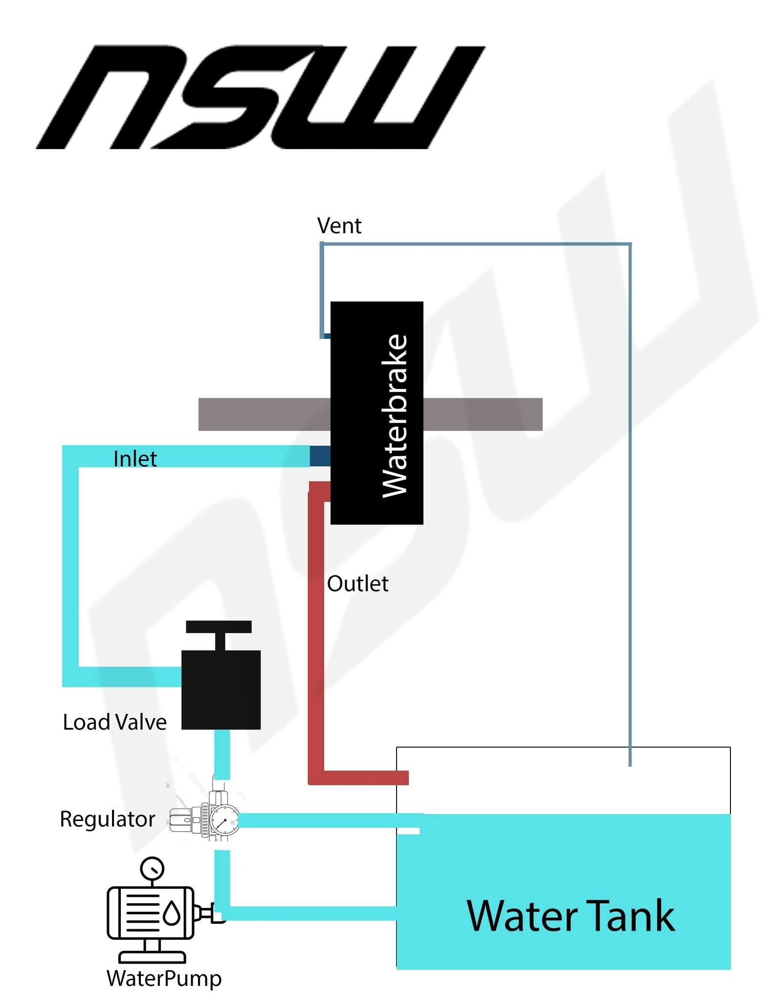
**Water Source → Pump → Regulator → Load-Control Valve → NSW Water Brake → Drain**
Advantages:
* simple
* cool inlet water
* minimal cooling equipment
Disadvantages:
* high water consumption
* drainage requirements
* impractical for repeated high-power testing in many locations
---
# Closed-Loop Water Systems
A closed-loop system recirculates the water.
Typical arrangement:
**Reservoir → Pump → Regulator → Load-Control Valve → NSW Water Brake → Cooling System → Reservoir**
The cooling system may use:
* cooling tower
* radiator
* heat exchanger
* industrial chiller
The reservoir alone should not be considered an unlimited heat sink.
Repeated high-power pulls can increase bulk water temperature very rapidly.
---
# Pressure Regulation
Stable water pressure is extremely important for repeatable dynamometer testing.
If pump pressure changes significantly as flow changes, the relationship between control-valve position and absorber load also changes.
A properly sized pressure regulator allows the control system to operate from a much more predictable hydraulic supply.
For electronic auto-load operation, stable supply pressure becomes particularly important because the controller continuously adjusts valve position to maintain RPM or sweep rate.
---
# Supply Plumbing
Large pumps cannot overcome badly undersized plumbing efficiently.
Pressure losses increase rapidly with water velocity.
For larger NSW systems:
* avoid unnecessary elbows
* avoid restrictive fittings
* avoid undersized hoses
* use full-flow valves
* keep suction plumbing especially unrestricted
* use gradual transitions where practical
* minimize unnecessary hose length
The pump inlet should never be starved.
Cavitation at the pump can dramatically reduce available water flow.
---
# Discharge Plumbing
The outlet side of the water brake must also flow freely.
Restrictive discharge plumbing can create excessive backpressure inside the absorber.
Use appropriately sized outlet plumbing and avoid unnecessary restrictions.
Where an NSW brake provides multiple outlet positions, use the outlet configuration specified for that particular absorber and direction of rotation.
Never assume that increasing outlet restriction is an acceptable substitute for proper inlet/load-valve control.
---
# Recommended Instrumentation
Every serious NSW dynamometer installation should include:
**Pump discharge pressure gauge**
**Dynamic pressure gauge near the load valve**
**Water flow meter**
**Brake inlet temperature sensor**
**Brake outlet temperature sensor**
These measurements make troubleshooting dramatically easier.
If the brake cannot achieve expected torque, the operator can immediately determine whether the problem is related to:
* insufficient flow
* pressure loss
* excessive water temperature
* valve restriction
* plumbing restriction
rather than incorrectly assuming that the absorber itself is undersized.
---
# Critical Pump-Selection Rule
Never select a water pump from its advertised maximum GPM alone.
A pump might be advertised as:
**100 GPM**
but produce that flow only at nearly zero pressure.
At 60 PSI it may deliver substantially less.
The correct specification is:
## Required GPM at Required PSI
Always examine the manufacturer's **pump performance curve**.
For example, if the dyno requires:
**75 GPM at 50 PSI**
the pump must actually produce at least 75 GPM at approximately 50 PSI after accounting for system losses.
---
# NSW General Recommendation
For smaller applications, use the following minimum references:
**20 HP → 1 GPM @ approximately 12 PSI or higher**
**160 HP → 8 GPM @ approximately 15 PSI or higher**
**200 HP → 10 GPM @ approximately 18 PSI or higher**
For larger and high-power NSW installations, use:
## Pump capacity up to approximately 15 GPM per 100 HP at approximately 60 PSI.
Always provide additional capacity where practical.
The final water system must be sized according to:
**Horsepower + Torque + RPM + Test Duration + Inlet Temperature + Brake Configuration + Plumbing Losses**
---
# Final Engineering Principle
A water brake can only absorb power if the water system allows it to do so.
A large absorber connected to an inadequate water supply becomes a small absorber.
A correctly sized absorber connected to a stable, properly regulated high-flow water system becomes a precise and highly controllable engine-development tool.
## NSW Water-Brake Systems
**3" | 5" | 7" | 9" | 11" | 13" | 16" | 19"**
**Correct Brake. Correct Water Supply. Correct Load Control. Repeatable Results.**